Thursday, November 25, 2010

Energy3D: Design, print, cut, assemble, and test

Figure 1: Designing a building with
Energy3D.

We have come close to release an alpha version of Energy3D, a computational building science laboratory for simulating energy flow and designing energy efficiency. This program will allow you to design a building in a What-You-See-Is-What-You-Get style in 3D, just like Google SketchUp, and then evaluate its energy performance.

The alpha version will feature the Blueprint Wizard, which automatically deconstructs a 3D structure into 2D pieces, figures out which pieces are on the same 2D plane, generates a layout of all the planes, calculates the necessary lengths and angles, and prints them on a sequence of pages. Every piece is numbered and annotated with calculated geometric information adequate to guide students to cut it from provided constructional materials such as paper or foam board. The entire deconstruction process is animated so that the user has an intuitive understanding of the relationship between a house and the pieces in the blueprint.
Figure 2: Cutting and assembling the
building shown in Figure 1.

Students also have an option of fitting designs to the dimensions of constructional materials. For example, one option is to assemble a house using printer paper. If students select this option, Energy3D will automatically rescale every piece to guarantee that the largest piece can fit an A4 page and all the others will be proportionally rescaled accordingly. In this case, the texture and all the marks on a piece will be printed out, making it possible for students to construct a physical scale model that looks just like its computer counterpart.

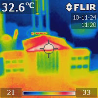
Figure 3: Testing the scale model under
a table light and observing its thermal
signature with an IR camera.
If students are not sure where a piece is located during assembly, they can go back to Energy3D and click on the corresponding virtual piece in the 3D computer model, which will then be highlighted to indicate its position. Thus, the software tool remains useful during the hands-on construction. If any revision is needed after a physical scale model has been constructed, Energy3D’s blueprint feature can help students evaluate whether a modification is feasible by calculating how many pieces will need to be changed and whether there will be enough materials to make the changes.

Energy3D is developed by Drs. Saeid Nourian and Charles Xie and made possible by a grant awarded to the Concord Consortium by the National Science Foundation.

Tuesday, October 26, 2010

An infrared view of a popular chemistry experiment

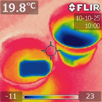
Figure 1. An IR image of a freshwater
cup and a saltwater cup after an ice
cube was added to each.
Will an ice cube melt faster in freshwater or saltwater? Why do we salt the road in water? How does an iceberg melt and how might it affect the ocean currents? All these curious questions are wonderful for students to explore. And they are very easy to do.

However, the science behind these questions are not that easy. To explain the results, we will probably need some reasoning at the molecular level, which is not at all easy for lower-grade students. But that is what we hope them to learn. These explorations require not only hands-on but also minds-on, which is why they are so great. 

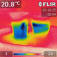
Figure 2. An IR image take after four
minutes showing the convection in
the freshwater cup.
They are not obvious at first glance and often can be counterintuitive. If you google "ice melts slowly in saltwater," you can find a lot of discussions--and debates as well. Many students and teachers were confused by what they observed in such a simple system as an ice cube floating in a cup of saltwater. Most of the discussions were, however, merely based on theoretical deductions.

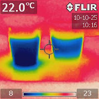
Had they had an IR camera, the thermodynamic processes would have been much more obvious. Figures 1-4 show a series of IR images taken to reveal what happened in the two cups after an ice cube was added.

The IR images show that ice molt faster in freshwater because cold molten water can sink to the bottom and warmer water at the bottom is pushed to rise. This process, called convection, runs continuously to carry heat from the whole cup to melt the ice cube.

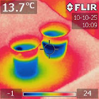
Figure 3. An IR image taken after
nine minutes showing the cooling
effect at the bottom as indicated by
the greenish halo.
In the case of saltwater, the cold water just sat at the top. The only explanation of this is that saltwater is denser so molten freshwater from the ice cube cannot sink, even if it is colder. Somehow, saltwater provides greater buoyancy that counters the thermal buoyancy.

Figure 4 shows that sixteen minutes later, the cold front still had not reached the bottom. This means that not only convection slowed down but also conduction was very slow.

Figure 4. 16 minutes later...
Recall our finding that a cup of saturated saltwater can spontaneously develop a temperature gradient from bottom up. This experiment provides a direct evidence that supports the theory that the temperature gradient can be created by the salinity. However, this evidence is not decisive, as the phenomenon reported here happens in an unsaturated solution whereas the small temperature gradient only exists in a saturated solution.

The puzzle still remains unsolved.

PS: Sprinkling some salt to an ice cube seems to accelerate the melting process. This seems to be in contradiction with the observation that ice melts more slowly in saltwater. This is where a lot of people are confused. The physics behind the two processes is different, even though they involve exactly the same chemical ingredients--just water in two different phases and salt. 

Monday, October 25, 2010

Which colors absorb more light energy?

Figure 1. A page with some color
strips under a table lamp. Click the
image to enlarge it to see the details.
We all know black objects absorb more light energy than white ones. What about red, green, blue, and any other colors? With an affordable infrared (IR) camera, this is very easy to figure out. (Update in 2015: There are now a few IR cameras that are priced under $300, such as FLIR ONE and SEEK THERMAL)

Use your word processor to draw and print some strips in any color you want on a page, as shown in Figure 1. Put the page under a table lamp (or sunlight) and let the light shine on it for 10 seconds. Then aim an IR camera at the paper. Figure 2 shows the results.

Figure 2. An IR image showing the
amount of light energy absorbed by
the color strips.
Obviously the black strip absorbed the most. But the red, blue, and green ones did not absorb much. Interestingly, the dark gray and purple ones seemed to have absorbed more energy than I would imagine.

I have to admit that I didn't know how other colors absorb light energy before doing this experiment. With an IR camera, you can easily check it out just on your own like what I did--for any color and any comparison.

If you have heard that Steve Chu, our Energy Secretary, has been serious about advising people to paint their roofs with light colors and Mayor Michael Bloomberg has agreed to answer the call in New York City, you may find this little experiment worth your while--you may pick a color that does not absorb a lot of energy yet it will be more colorful than white.

Updates in 2013: Links to my YouTube videos about this experiment:

Sunday, October 24, 2010

Visualizing convection without using ink

Figure 1. A top view of a floating
ice cube.
If you have done a convection demo using a container of water and some ink, you may have had to change the water after each demo since the ink had diffused everywhere, which may make the convection pattern less easy to observe. Depending on the size of your container, that is some work to do and some water and ink to waste.

Here is a greener and better way to do it--using an infrared (IR) camera. An IR camera shows hot and cold (typically) in red and blue colors, which can be considered as "IR ink" that can be seen only through an IR camera. With the tool, all you can do is to add some ice cubes or hot water to a container of water every time you need to do a demo. There is no need to change the water.
Figure 2. A side view of a floating ice
cube showing "cold fingers." 

One thing to notice is that you should not use a glass container--because it reflects off IR rays that will get into the image. A clear plastic one is the best as it does not reflect much and it allows you to observe what happens inside (if anything visible) with naked eyes.

Figure 3. A view from another side
showing the the cooling at the
bottom.
Figure 4. An IR image after hot water
was added to room temperature water
in a container showing hot water
tended to float atop.
Figure 5. An IR image of a fish tank
showing a clear pattern of
temperature stratification.

Friday, October 22, 2010

Salinity gradient vs. temperature gradient

Figure 1. The salinity gradient and temperature 
gradient observed in an open cup of saturated 
saltwater.
This is the fifth follow-up of my blog article: "A perfect storm in a cup of salt water?This investigation focused on the relationship between the salinity gradient and the temperature gradient. Is the temperature gradient caused by the salinity gradient, or the other way around? Both arguments seem to make some sense. On the one hand, one can argue that the salinity gradient stops the convection. On the other hand, warmer water tends to dissolve more salt. So we are in a chicken-egg situation.

Let's do an experiment to explore a bit further. I prepared two cups of saturated saltwater. One open and the other sealed. I let them sit overnight and then checked the salinity and temperature distribution the next day using Vernier's salinity sensor and temperature sensor. I did this by moving the salinity sensor and the temperature sensor together up and down in the saltwater. Figure 1 shows the results for the open cup.


Figure 2. The salinity gradient and temperature
gradient observed in a closed cup of saturated
saltwater. Note: The measurement was done
shortly after removing the seal.  Hence the results 
can be regarded as approximately those of the
sealed cup as the gradients will take a longer 
while to establish.
To measure the data for the closed cup, I first removed the seal and then quickly did the measurement. Since the salinity and temperature gradient would take some time to re-adjust after the seal was removed, we can pretty much assume that the results I got approximately reflect what would have been measured if the seal had not been removed. Figure 2 shows the results.

 The comparison of the results shows that the salinity gradient is about the same for the open and closed cup--the bottom is about 1.3 ppt saltier than the top, but the temperature gradients are quite different--the open cup measured about three times as large as the closed cup (0.3°C vs. 0.1°C). 


Due to the evaporative cooling effect, the overall temperature of the open cup is at least 0.5°C lower than the closed one.

What do these results suggest? Is it possible that a weak temperature gradient exists in a closed system that does not have the driving force of evaporative updraft?

Tuesday, October 12, 2010

Visualizing vapor pressure lowering

Figure 1. Two shallow plastic containers. 
The left one holds a lot of salt and the 
right one is plain water. A small amount 
of water was added to the left one.
This is the fourth followup of the blog article: "A perfect storm in a cup of salt water?" that started this journey of discovery.

The vapor pressure lowering is an effect that says the water vapor pressure above saltwater is lower than that above freshwater. This is more generally described by Raoult's Law, which states that the vapor pressure of an ideal solution depends on the vapor pressure of each chemical component and the mole fraction of the component present in the solution. Since the sodium and chlorine ions hardly evaporate, the vapor pressure above saltwater comes from the evaporation of water molecules.

The molecular mechanism behind the vapor pressure lowering is easy to understand--the ions stay in the way of water molecules and slow down the rate of their evaporation and, in the case of salt, they even act to attract the water molecules and prevent them from leaving the solution.
Figure 2. An IR image of the two shallow
containers right after water was added to
the salt one on the left.

Let's try to use infrared (IR) imaging to visualize this process. Prepare two plastic containers like the ones shown in Figure 1. Add plenty of salt to one of them and some water to the other. Then add some water to the salt one. Figure 2 shows an IR image just after water was added. The image shows that the system absorbed heat while salt was being dissolved.

Figure 3. An IR image after half an hour
showing that the evaporative cooling
effect of the saltwater container is weaker
than the pure water one.
Let the containers sit for about half an hour and then take another IR image. Figure 3 shows the result. Interestingly, the colors reversed. Now, the saltwater container appears to be warmer than the pure water one.

Figure 4. An IR image after a few hours
showing that the contrast of colors
became greater.
Wait for a few hours and then come back to take an IR shot. Figure 4 shows that the temperature difference became greater.

How to interpret these results? There are two mechanisms that cause the temperature difference.

One is the vapor pressure lowering mentioned above. Using a Vernier relative humidity sensor, one can confirm that the humidity above the saltwater is lower than that above the freshwater. This means that the evaporation weakens above saltwater, which reduces the cooling effect.

The other is the crystallization of salt that releases heat. The evaporation of every water molecule weakens the ability of the solution to hold ions. As water constantly evaporates, a corresponding amount of ions must return to the crystalline form--mostly at the bottom because the contact area with the wall is much smaller compared with the contact area with the bottom. This process releases heat at the bottom. Since the saltwater is very shallow, the heat conduction may happen fast enough so that the crystallization heat will pass to the surface of the saltwater--even if convection may be insignificant with such a shallowness--and make it even warmer on top of the weaker evaporative cooling effect. This effect, which is totally based on molecular reasoning, is yet to be confirmed by an experimental method.

The vapor pressure lowering process and the crystallization process in this system are intertwined. If evaporation slows down (absorb less heat) due to salt, crystallization slows down (release less heat) too. The small amount of crystallization heat transfers to the surface and slightly increases the evaporation rate, which in turn causes slightly more ions to crystallize. The two processes manage to keep the saltwater container warmer than the freshwater container. But we still don't know which process contributes more. The question is, without the crystallization heat, can the IR image of the saltwater be as warm as it appears to be? How can we separate the two effects? Sealing the containers to stop evaporation doesn't work because that will stop crystallization as well.

Why do I insist on the theory of crystallization heat? Not only because it is logical. If we look at Figure 2, we will see that the effect of heat of solution is pretty significant. In order for salt to dissolve in water, some heat needs to be absorbed. Now, when the reverse process has to happen, i.e., when the salt ions have to return to the solid form, the same amount of heat must be released--in a much slower pace because of the low rate of evaporation (compared with the rate of dissolving). This is just simply the rule of energy conservation at work. The chemical potential must act like a spring. Energy is stored when it is "compressed" and released when it "bounces back."

Most likely, I now think this mysterious effect in a cup of saltwater is an orchestration of many physical and chemical effects. The salt gradient in a saturated solution is yet another mystery to be uncovered: the salinity gradient exists only in a saturated solution but not in any unsaturated solution.

A small cup of saltwater may contain a lot of physical chemistry! Stay tuned for more follow-up experiments.

Thursday, September 23, 2010

Mystery solved?

This is the third followup of the blog article: "A perfect storm in a cup of salt water?"

I woke up last night with a perfect explanation for the mysterious temperature gradient observed in a saturated salt solution. It is the recrystallization of salt at the bottom of the cup that releases the heat.


Since water molecules are constantly evaporating from the surface of the solution, a corresponding amount of ions must return to the crystal form at the same time--because a reduced amount of water in a saturated solution in the cup cannot take them any more. This most likely occurs at the bottom since the surface of the precipitate already provides a perfect ground of crystal growth. When ions adhere to the surface of a crystal, heat is released. The amount of released heat is approximately equal to half of the cohesive energy of the salt crystal (because it is a surface adhesion), which may be quite high because of the strong electrostatic attractions in the ionic crystal. The released heat transfers to the solution near the bottom and, together with the evaporative cooling effect on the surface, creates the temperature gradient we observed. The entire process runs continually across the solution because of the diffusion of water molecules and ions driven by their concentration gradients: the concentration of water/salt becomes lower/higher at the surface when water evaporates. 

There are four evidences that support this theory:
  1. The temperature gradient disappears when we sealed the cup, because that stopped the evaporation at the surface as well as the recrystallization at the bottom.
  2. We observed no temperature gradient in an unsaturated solution because there is no recrystallization process.
  3. The temperature hiked when the sensor touched the salt deposit at the bottom.
  4. This temperature gradient lasts for a long time because this process will continue until all the water molecules evaporate.
Now, how can we make use of this effect to produce clean energy? As we produce sea salt by using solar energy to evaporate the water in brine anyway, might it be possible to harvest the energy released from the crystallization process? This seems like a stone that kills two birds: generating electricity while producing salt.

The diagram above illustrates the energy cycle of a saltpan/ionic power plant combo. This design is based on a chain reaction that involves two phase changes in a salt solution to convert solar energy into electricity through the ionic potential.

PS: I found in Wikipedia the concept of solar pond that uses a large pool of saltwater to collect solar energy. I think its mechanism is different from what I discussed above. I have had no luck reproducing the effect of a solar pond in a cup yet.

Monday, September 20, 2010

The temperature gradient exists only in a saturated solution

This is the second followup of an earlier blog article "A perfect storm in a cup of salt water?"

I did an experiment to investigate the relationship of the salt concentration with the mysterious temperature gradient in a cup of salt water. The experiment was to measure the top-bottom temperature differences in three cups of salt water: low-concentration, medium-concentration, and saturated solution. In the saturated solution, there is a salt precipitate at the bottom of the cup. In all measurements, a fast-response temperature sensor was moved up and down in a cup. And the solutions had existed for over 100 hours to ensure that the salt was completely dissolved and the systems had reached thermal equilibrium with the environment.

The results shown in the graph above clearly indicate that the temperature gradient exists only in the saturated solution. The two unsaturated solutions exhibit no appreciable temperature gradients and measure approximately the same temperature with plain water.

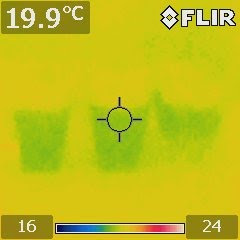
The results were confirmed by an IR image shown above (from left to right: low-concentration, medium-concentration, and saturated).

This experiment suggests that there is probably no ion gradient in an unsaturated solution. An unsaturated salt solution has the same temperature everywhere and that temperature is the same as that of the plain water, whatever its concentration is. I originally expected that an unsaturated solution would have a temperature gradient more or less proportional to the salt concentration, as would a colligative property. This surprising result made me think that the prime suspect is the salt precipitate at the bottom of the cup. We know there is a lot going on on the surface of the precipitate layer. The dissolving and crystallization never cease. It is just that the two processes reach a dynamic equilibrium--the rate of dissolving becomes the same as the rate of crystallization.

Let's think a bit more about the meaning of this experiment. Notice that the temperature curve of the saturated solution lies entirely between that of the ambient temperature and that of the pure water temperature in the graph. This means that the existence of the precipitate somehow weakens the evaporative cooling effect, and probably the evaporation process itself. Why would the evaporation of water at the top of the solution slow down in the presence of some precipitate at the bottom? Exactly how does this process contribute to the temperature gradient existing in the solution?

We can plausibly reason that the rate of evaporation decreases because the ions somewhat act as binding agents that hold the water molecules more tightly through the strong electrostatic attractions. This is known as the water shell effect—water molecules are attracted to an ion and form a dynamic shell around it. As a result, it is more difficult for water molecules to leave the solution to evaporate. But this picture cannot explain why there is virtually no difference between the temperature of a cup of pure water and the temperature of a cup of unsaturated salt water.

It seems the mystery is far from being uncovered. While clarifying a few things, this experiment makes the phenomenon more baffling. Stay tuned for our next investigation.

In terms of its other implications, there is one thing that we can rule out now. There is no such effect in the ocean, as sea water is not saturated.

Tuesday, September 14, 2010

Evaporation is a driving force

This is the first followup of the blog article last week "A perfect storm in a cup of salt water?".

Several people including Bob Tinker, John Loosmann, and Einar Berg suggested that it was the evaporation of water that drives the observed persisting temperature gradient. It turned out that they were right. After sealing the salt cup with plastic wrap and leaving the three cups for 24 hours, their thermogram shows the sealed cup vanishes from the infrared image (see the image to the right--the sealed salt water cup is in the middle, which is invisible). This means that the temperature everywhere in the cup is the same as the ambient temperature. The infrared image also shows the baking soda cup, which has not been sealed, continues to show a temperature gradient.

Now, we have to explain why the pure water cup shows a cool infrared signature. So I added a sealed pure water cup. The thermogram to the right shows that the sealed pure water cup vanishes in the infrared image (the sealed water cup is on the right of the thermogram), whereas the open pure water cup shows a cooler image for the part filled with water. Interestingly enough, the upper part of the cup that does not have water contact is constantly almost 1°C warmer than the filled part. This temperature gradient is clearly shown in the infrared image below. Why is the temperature gradient across the water line on the surface of the plastic cup so sharp?

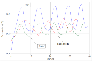
Now go back to the evaporative updraft force. At this point, we only know that cutting off evaporation shuts down the energy loop. We still do not know how what happens under the water line in the salt water cup. The following graph clearly shows that this effect exists in not only a salt solution, but also a baking soda solution and a sugar solution.

We can suspect that the ion concentration gradient is another driving force for this energy circuit. This will be our next step of investigation. Stay tuned.

Friday, September 10, 2010

A perfect storm in a cup of salt water?

I was bothered by an experiment I did recently about the temperature distribution in a cup of salt solution. I added a few spoons of table salt and baking soda in two cups of water to create two saturated solutions. Then I left them sit there for a few days, along with a cup of plain water. When I came back and aimed my infrared camera at them, I saw something quite puzzling: in the two cups of solution, the bottoms were always about 0.5°C warmer than the tops (see the IR image above)! In contrast, a cup of plain water did not show this temperature difference--the temperature was the same everywhere just as expected.

Exactly what kind of chemical force sets up this temperature gradient? We all know that warmer water should rise and colder water should sink, and eventually the convection stops and the temperature becomes the same everywhere. But this is apparently not true in the presence of salt solute. I feel this has to do with gravity. It must be gravity that causes a concentration gradient of the solute, which in turn results in the temperature gradient. But I am not sure how exactly this happens. I have no idea what energy source feeds this temperature gradient. Don't forget that the cup material tends to eliminate it through heat conduction and the air through convection. There must be an invisible hand that counters all these thermodynamic forces. This seems pretty amazing to me.

To make sure that this is not an effect of infrared radiation, I confirmed the result by sticking a sensitive temperature probe into the solution and moved it up an down for a few times. The image below is the 60-second result recorded by the temperature probe, which clearly agrees with the IR image.

This is an example that, once again, shows the power of infrared imaging. I would not have noticed there was such a temperature gradient in a solution without my infrared camera. The infrared camera, in just one simple shot, captured the salient and subtle details that reveal very complex physics, which I still do not understand.

What is the significance of this result rather than a tempest in a teacup? Might the temperature gradient be used to generate a voltage gradient, which in turn generates electricity? In other words, might this be some kind of battery that is a 100% clean energy source?

The ocean is a gigantic solution of salt. Half Celsius of temperature difference in the ocean translates into an enormous amount of energy. Might there be such an effect in the ocean?

Followups:
1) Evaporation is a driving force
2) The temperature gradient exists only in a saturated solution
3) Mystery solved?
4) Visualizing vapor pressure depression
5) Salinity gradient vs. temperature gradient
6) An evidence from an ice cube

Sunday, September 5, 2010

Infrared imaging for chemistry education

Infrared (IR) imaging is a technique for seeing heat based on detecting thermal radiation (mostly IR) an object emits. It used to be a very expensive tool only affordable to guys in military and secret services where money is not a problem.

You can now buy "lower"-grade IR cameras with $1,000-$2,500, which are pretty cool (thank you for lowering down the prices, FLIR and FLUKE!). There is a vast market for this technology. Engineers and technicians buy them primarily for checking heat flow in building, electrical systems, and mechanical systems. Companies also use them to do quality assurance and condition monitoring.

I have been digging the educational potential of IR imaging lately. I feel that the tool can be very useful in education. Compare it with a microscope. Both can be used to see something invisible. In the case of a microscope, it is things that are too small to be seen. In the case of an IR camera, it is things that our eyes cannot detect. It is obvious that students need a microscope to see small things. But perhaps we can also rationalize the need for an IR camera in the classroom? What are the most important things that IR imaging can teach?

Obviously there is heat transfer. I have recently written a paper about this. But I don't want to just do the evident ones. So I have been thinking about how to broaden its applications. A direction I am taking now is its applications in chemistry, where heat is a central concept. You probably still remember that your high school chemistry teacher always wanted you to remember how much heat is released or absorbed in a chemical reaction. If a reaction produces a dramatic effect, such as a bang or a flash or a flame, then you probably were impressed. What about those reactions that mostly go unnoticed unless some sensitive methods are used to show them? For instance, most biochemical processes are pretty "calm." How does one "see" or "hear" them?

I have done an experiment that uses an IR camera to show evaporation and condensation, as mentioned in the paper. The above IR thermogram shows what happened when a piece of paper was placed on top of a cup of water. The paper did not fully cover the cup. What we see from this IR image is a cooler area that shows the evaporation process of the water in the cup and a warmer area that shows the condensation process of the water on the other side of the paper.

Last week, I did another experiment to prove that it can also be used to visualize dissolving. This experiment is introduced in a short article. The image to the right shows the thermograms of three cups: pure water, table salt solution, and baking soda solution, shortly after table salt and baking soda were added to two of the cups originally filled with pure water.

I am hoping to devise more chemistry experiments to prove the versatility of this powerful tool in making mysterious things in chemistry visible. I intuitively feel that this tool, which is essentially a bundle of thousands of IR thermometers, may be able to release students from tedious lab procedures and make chemistry experiments easier to conduct and fun to look at.

Update in 2012: The idea in this post has grown into a website: http://energy.concord.org/ir/. Check it out!

Monday, August 16, 2010

Who says kids cannot invent?

I was recently involved in a few pilot field tests in which high school students were challenged to build an energy efficient scale model house. We observed something amazing. Initially, I was worried that students may end up building houses that are so similar to each other that the entire research will be invalidated. But that did not happen.

In one field test, a group of students created a pyramid and discovered an effect that I would call "a heat funnel." The images to the right show the pyramid heated by a 40W light bulb on the floor inside and an infrared signature showing the equilibrium temperature distribution. The students observed that the temperature at the tip of the pyramid reached nearly 150°C--enough to boil water! This amazing heating effect is due to the fact that hot air rises to the top in a way similar to how water flows down in a funnel. Just like the bottleneck of the funnel records the highest speed of water flow, the top of the heat funnel records the highest temperature of heat flow. The water funnel is usually explained using the conservation of mass, whereas the heat funnel can be explained using the conservation of energy. The density of thermal energy must increase when the heat conduit narrows in order for energy to conserve. Therefore, the temperature at the tip can be very high because its cross section is very small.

Although they did not expect the temperature at the tip to be so high, the students were fully aware of the convection effect, because they cut some slits at the bottom of the pyramid to let fresh air in in order to keep the air flow through it (you can see a slit from the photo on the left). This is the stack effect that drives a chimney. At the top of the pyramid, the hot air just exits through the tip, which naturally has small passages for the air because it was not perfectly sealed. Had students had a sensitive air speed meter, they would have observed a small but appreciable jet stream coming out from the tip (would they?), just like steam from the vent of a cooking pot.

In another field test, a group of students created a sliding roof that can provide overhang shading in summer and increase roof insulation in winter (see the images to the right).

I must confess that, as a physicist, I have never heard of or thought of the heat funnel effect until I saw it in the classroom. Pondering about this effect, I realized that it might be non-trivial and could have some engineering implications. For example, might this effect be used to build some kind of solar updraft pyramid for generating electricity? I have heard that in the US there are huge solar power plants that utilize the optical focus effect to create high temperature to boil water, which in turn creates steam to push an electrical generator. How about a heat funnel generator that will work sunny or cloudy?

The sliding roof invention is impressive in that the students figured out an engineering solution that solves two problems: winter insulation and summer shading. The students also had an idea of putting solar panels on the sliding roof and the base roof. This smart design, which increases the solar reception area, will turn the unwanted solar heat into electricity instead of reflecting it off. This is not just a single solution that solves one problem. This is a stone that kills three birds. Isn't this exactly what we strive to teach in our engineering classes?

These inventions of students should convince you that students are not just learners. If we give them creative tools and interesting projects, they can be inventors as well. Sometimes, their inventions will surprise even seasoned scientists and engineers. Science and engineering education should make more opportunities for these young inventors to rise to the top.

Sunday, February 14, 2010

MW applets and MWScript-JavaScript interactions


Now that you can publish a Molecular Workbench simulation as an applet and embed it on your web page, you may be wondering how you can control it and get data in and out. It may be interesting for web developers who would like to link an existing Flash animation with a molecular dynamics simulation in MW. For example, when the visitor clicks something in the Flash animation, a molecular dynamics simulation will pop out to show the molecular mechanism of what is going on underneath.

With MW, this can now be done using MWScript and JavaScript. MWScript is a scripting language used in MW to support modelers and animators to design simulations. The model builders in MW do have some simple GUI for building models and designing simulations, but their functionality is limited (as with any GUI). Syntactically, MWScript is a cousin of JmolScript, which supports scripting with the popular Jmol molecular viewer. So anyone who is already familiar with JmolScript may find it easy.

Before we talk about scripting, let me show you how to set up an MW applet on your web page. If you just want to show an existing MW simulation from mw2.concord.org (which hosts MW) on your web page, just embed the following applet code within the body of your HTML file:

<applet id="applet_id"
archive="http://mw2.concord.org/public/lib/mwapplet.jar" 
code="org.concord.modeler.MwApplet" codebase="http://mw2.concord.org/public/" 
width="100%" height="500"> <param name="permissions" value="all-permissions"/> 
<param name="script" value=
"page:0:import http://mw2.concord.org/public/student/classic/motion/undershotwaterwheel.cml"/>
</applet>
In the above example, I have randomly chosen an existing simulation from MW to show how this works. If you want to show other simulations, just replace "http://mw2.concord.org/public/student/classic/motion/undershotwaterwheel.cml" with whatever else.

This following shows the embedded MW applet specified by the above code:


This is very easy to do. But it has a limitation. Suppose you have created an MW simulation of your own and the name of the main file is "simulation.cml" (an MW simulation has other files associated with it as well). Now you have to upload the files to the Web. If you use its URL in the embedding code, the MW applet will not load it. Because of a good security reason, an applet is allowed to read files from only the same code base where the Java executable is located (in this case, http://mw2.concord.org/public/lib/mwapplet.jar).

To avoid this problem, you would want to have your own code base instead of using mw2.concord.org. First, you download the jar file: mwapplet.jar to the same folder where "simulation.cml" and the HTML file sit. Second, change the embedding code to:
<applet id="applet_id" archive="mwapplet.jar" 
code="org.concord.modeler.MwApplet"  codebase="http://mw2.concord.org/public/"
width="100%" height="450"> <param name="permissions" value="all-permissions"/> <param name="script"
value="page:0:import simulation.cml"/>
</applet>
Having done these, you just need to make sure to also upload "mwapplet.jar" to the same web folder where "simulation.cml" has been uploaded to.

If you have done these and succeeded in getting an MW applet to work properly, let's see how to get it to work with JavaScript as well. First, download this file: mw.js to the same folder. Second, put the following script declaration in the header of your HTML file:

<script type="text/javascript" src="mw.js"></script>
The MW applet is now ready to interact with JavaScript. The applet works offline as well, so you can conveniently test your JavaScript before deploying the whole thing to the Internet, by just double-clicking on the HTML file and see how it works.

There are currently three types of interactions between MWScript and JavaScript.
  • Use JavaScript to send MWScript to control an MW applet
  • Use JavaScript to feed data to an MW applet
  • Use JavaScript to get data out of an MW applet
The runScript(id, script) method in mw.js can be used to send MWScript to an MW applet with the specified ID. An MW applet is an MW page that can have multiple models, though in practice you would only use one model per applet. To specify which model you would like to send the MWScript, you have to following the following protocol:

[model type]:[index or UID of model]:[script body]

For instance, mw2d:1:run instructs the first model within the MW applet to run. You can pass a variable from JavaScript to MWScript by concatenating the variable with a script command. For example, var temp = 300; runScript("applet_id", "mw2d:1:set temperature " + temp) sets the temperature of the system to be 300 K.

The get command in MWScript was specifically designed to fetch data out of an MW applet. For instance, you can get the temperature by using the following code: var temp = runScript("applet_id", "mw2d:1:get %temperature");.

This page demonstrates all these three types of interactions with one applet. It is inconvenient for me to mix code in this blog as it interferes with the blog's setup. When you go to that page, you can view the page source to see the JavaScript code. If you have Firebug, it can also be used to view the code easily.

For more information about MWScript, go to http://mw.concord.org to launch the standalone application and check out the "Script" section in the User's Manual.

Saturday, January 30, 2010

Publishing Molecular Workbench simulations as applets

For a while I have been asked whether or not an MW simulation can be made to run directly within a browser page instead of a pop-up window. Several collaborators would like to deploy MW simulations within their web portals or delivery systems. For them, embedding a simulation within a web page is desirable. The current way of using the Java Web Start to launch an MW simulation sometimes irritates users as it can appear to be yet another kind of annoying pop-ups.

So I did some work in the past week to make it possible for users to save an MW page as an applet, which can then be deployed anywhere without having to rely on my company's server. This is always good for the integrity of a web site, as no serious web developer wants to depend on other people's servers to be up and running forever.

Here are some demos:


This new mechanism of publishing MW simulations provides an option for people who want to integrate MW simulations with their web applications, if they don't mind the relatively slow loading speed.

Monday, January 11, 2010

Energy2D: Interactive computational fluid dynamics

Computational fluid dynamics (CFD) uses numeric methods to study any natural phenomenon and solve any engineering problem related to fluid flow. It has been an indispensable tool for many engineers. Mature, powerful CFD products are available nowadays. While these products are very useful tools for engineers, they were not designed for kids to play with. Understandably, the business community lacks the financial incentive to push the agenda of making a product friendly to students for learning science and engineering. With all these years passed while CFD products got better and better, all the wisdom developed for modeling and understanding the natural and man-made systems never got spread to schools in a satisfactory scale.

This tragedy was, in part, caused by the unfortunate fact that few people in the education community had realized the enormous power of CFD for teaching science and engineering. Educators had a very good reason for not seeing it, because the power has never been brought close enough to matter in their professional careers. Most CFD tools are either too complicated to use or do not deliver the needed visual effects and user interfaces to matter. This is an issue that cannot be simply said solved by sending a demonstrator from the CFD community to the education community. Talking and showing are cheap. To bridge the gap, we need actions that will truly make a difference.

Supported by the National Science Foundation with an urgent need for educating young students with energy science and technology, we are developing a versatile CFD package suitable for teaching the scientific and engineering principles related to energy flow, particularly about energy-efficient passive solar buildings. The package consists of two programs called Energy2D and Energy3D, respectively, for the 2D and 3D versions of the CFD simulator.

Energy2D and Energy3D are based on solving the heat equation for modeling thermal conduction, coupled with the Navier-Stokes equation for modeling convection. A ray-tracing method is used to model radiation. The minimum requirement is that the simulation must run fast enough to be interactive so that students can play with it.

After a few weeks of work, I came up with a primitive version of Energy2D. The following two screenshots show that if the obstacle has a small cross section against the flow, turbulence will not occur.

It turned out that writing an unconditionally stable heat solver was not a big deal. After all, it is just a simple diffusion equation that can be easily solved using an implicit method.

Writing a fluid solver is more challenging as it is non-linear (which is where all the fun comes from). I played and tested Jos Stam's fluid solver, which is based on an unconditionally stable Semi-Lagrangian method that is also used in weather prediction. Unfortunately, the solver is covered by a pending patent that we didn't succeed in convincing the current patent owner to license to us in any way--open-source or not. So I had to give up Stam's method and sought to reinvent the wheel.

I implemented the MacCormack method, which turned out to work fine for now. Compared with the Semi-Lagrangian method that achieves its stability by overdamping the fluid, the MacCormack method has no overdamping problem so it has to suffer from the stability problem. As a side note, I also found that after using the vorticity confinement method to re-inject vorticity to the solution of the Semi-Lagrangian method to make it more turbulent, it would also suffer from the stability problem. There seems to be no free lunch in seeking a fast, yet accurate, fluid solver.